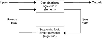

It's tempting to think that this circuit has just two states – on and off – but that's not so. In our digital circuit, the light will switch on the next clock edge following the change in input. The switch has one input and one output: the output changes state just once for each pulse on the input, however long. It stays on when you release the cord, but goes off when the cord is pulled for a second time. The first time you pull the cord, the light comes on. Let's design a digital implementation of the kind of pull-cord light switch that is often found in British bathrooms. For the circuit to work correctly we must set the clock period T so that T ≥ t 1 + t 2 + t 3 + t 4, and the same for all combinational paths.Īnother timing calculation, involving contamination delays, is needed to put a bound on the amount of clock skew the circuit can tolerate. In the diagram, time t 1 is the propagation delay of the first flip-flop times t 2 and t 3 are the propagation delays of the two gates, and time t 4 is the setup time of the second flip-flop. If you search for datasheets of SSI chips, you can find equivalent circuits for flip-flops in terms of gates: but you shouldn't take them too seriously, because the dynamic behaviour of a flip-flop over time cannot be deduced from the static behaviour of a collection of logic gates.īefore we look at the problem of specifying and designing sequential circuits, we should work out the behaviour of a given circuit.ĭelays accumulate along each combinational path. Most flip-flops have an 'asynchronous reset' input that can be used to ensure this. We will assume the initial condition z 0 = 0. (Other kinds of flip-flop exist where the next state depends on the current state as well as the input – they used to be popular with SSI logic, because they sometimes lead to simpler designs.) We could spell out this behaviour in a kind of truth table, though it is a bit boring.Īs you can see, the next state is always the same as the input, whatever the current state might be. The D-type always produces as its output the value that its input had during the previous clock period The little triangle in the circuit symbol means that the state of the flip-flop can change only when the clock signal makes a transition from 0 to 1 – a positive-going clock edge.īecause signals can now change over time, each wire will now carry a sequence of Boolean valuesĬombinational gates compute the same function in each clock period: for an AND gate,

We will concentrate on fully synchronous designs where all the clock inputs of flip-flops are connected to a single, regular, global clock signal – perhaps derived from a quartz crystal. The flip-flop has two inputs, d and clk, and one or two outputs, one called q, and perhaps (for convenience) another equal to ¬ q.


 0 kommentar(er)
